Setting up a virtual 4-way on Home Assistant lets you pair three Zooz switches or dimmers to control the same light—without needing a wired connection between the switches. In this setup, the main switch or dimmer is rewired as a single pole, while the remote units connect to power, neutral, and ground only.
There are three ways to program this configuration:
Direct Association (recommended), Central Scene, or Rules (scenes). Direct Association allows the switches to communicate directly outside of the hub—ideal when all switches are added via the standard Z-Wave mesh network (this will not work for switches that are included using Z-Wave Long Range).
Meanwhile, Central Scene relies on hub communication and scene commands, a perfect choice when using Z-Wave Long Range.
Rules/scenes are the last option, and only recommended if you're using a hub that does not support Direct Association or Central Scene.
This guide walks you through all methods, so you can choose the best fit for your setup.
Please ensure you have followed the correct wiring diagram for the virtual 4-way. There cannot be a wired connection between the smart switches.
1. Direct Association (Recommended)
IMPORTANT NOTES
-
Z-Wave JS UI: Direct Association is only available on Home Assistant when using the Z-Wave JS UI integration. It is not available on the standard Z-Wave JS integration.
-
Mesh Only: Direct Association can only be used when the switches are included to the hub using the standard Z-Wave mesh protocol. Z-Wave Long Range by nature does not allow for device-to-device associations.
-
Same Security Level: All switches must be included with the exact same level of security in order to be associated (all using S2A or all using no security)
Our unique programming design allows our switches to be directly associated while still maintaining the correct status on each switch. Direct Association allows the switches to be linked together and communicate outside of the hub. Your Z-Wave system needs to support this feature and both switches need to be added to your hub with the same level of security via the mesh (no ZWLR).
We recommend that you use the ZEN71 On/Off switch, ZEN72 Dimmer, ZEN75 Heavy Duty Switch, ZEN30 Double Switch, ZEN32 Scene Controller, or ZEN35 Scene Dimmer models with the latest firmware for this scenario and program them according to the instructions below for the best experience. The ZEN77 (as well as the ZEN73, ZEN74, and ZEN76) can be used in the virtual set-up, but we would recommend these units be wired in the main box with the direct connection to the load due to their patented internal design.
To start, we recommend checking the firmware version on your dimmer/switch. The instructions are simpler if you are using firmware higher than 3.30; if your unit is a hardware VER 3.0, please update your unit to the latest available firmware for your hardware version before programming the association.
Dimmer/Switch Settings/Parameter Instructions
-
Main dimmer or on/off switch (connected to load): No changes in settings
-
Remote dimmer or on/off switch (not directly wired to the load): no changes in settings (as long as you are on firmware higher than 3.30).
- If you have an earlier firmware, you will need to set Parameter 7 to value 11 (ONLY if your firmware is earlier than 3.30; this will break the direct association if used on firmware 3.30 or later.
Set the Association
On/Off Switches:
Set the association for Group 2 (Basic Set On/Off) only, adding the device ID's for the other switch in the group. So, if switch A is your main switch and switch B is your remote switch, add switch B to Group 2 on switch A and add switch A to Group 2 on switch B.
-
IMPORTANT: The remote switch can then only be used from the paddles (you need to hide it in your interface not to trigger it via Z-Wave) while any Z-Wave or wireless control of the light needs to happen from the main switch A. This will ensure both devices stay in sync at all times.
Dimmers:
Set the association for Group 3 (Multilevel Set) only, adding the device ID's for other dimmers in the group. So if dimmer A is your main dimmer and dimmer B is your remote dimmer, add dimmer B to Group 3 on dimmer A and add dimmer A to Group 3 on dimmer B.
-
IMPORTANT: The remote dimmer can then only be used from the paddles (you need to hide it in the UI not to trigger it via Z-Wave) as any Z-Wave or wireless control of the light needs to happen from the main dimmer A. This will ensure both devices stay in sync at all times.
Z-Wave JS UI Association Fields Explanations
-
Endpoint (Source): This is the "brain" of the device sending the command.
-
For a single-switch device, this is always the Root.
-
For multi-channel devices (like the ZEN30 Double Switch), you must specify which physical part is talking: Endpoint 1 is the Dimmer, and Endpoint 2 is the Relay for the ZEN30 for example.
-
-
Group: This is the "type" of message being sent.
-
Lifeline (Group 1): Always reserved for the Controller (your Z-Wave stick) to report status.
-
Basic Set (Group 2): Sends a simple "Turn On" or "Turn Off" command.
-
Multilevel Set (Group 3): Sends specific brightness percentages (dimming).
-
-
Node (Target): The specific device ID you want to receive the command.
-
Target Endpoint: The specific sub-component on the receiving device that should react. This is only applicable for multichannel devices that have more than one endpoint. In most cases, this will stay as No Endpoint, unless the receiving device is a multi-channel device.
In our below example, we're using the ZEN71 On/Off Switch as the main switch (directly wired to the load) with the ZEN32 Scene Controller and ZEN75 Heavy Duty Switch in the remote boxes (connected to power line, neutral, and ground only).
In the control panel, ensure the three devices you are associating are included with the exact same level of security, and that both are included via the mesh network. The highlighted sections show matching security levels and that all 3 units are included via the mesh (blue Z-Wave icon under protocol).
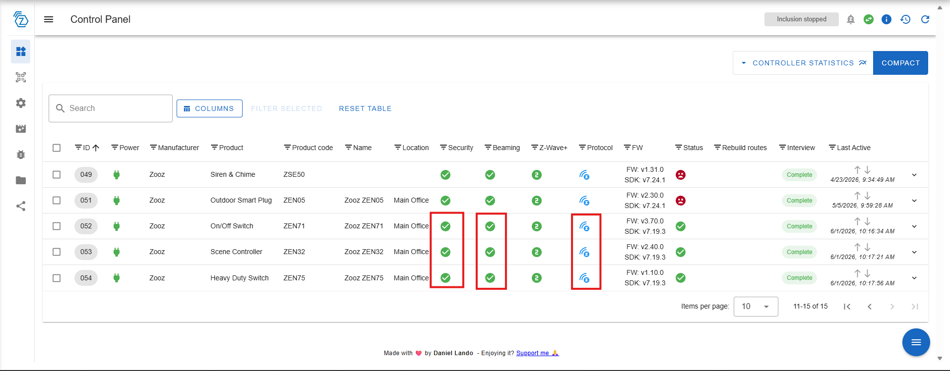
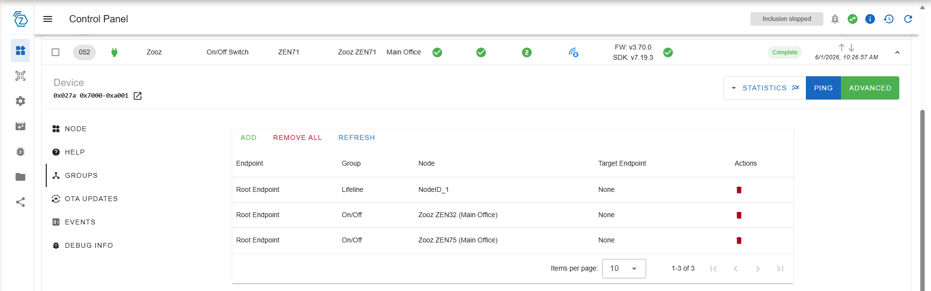
Click the drop down arrow on the right for the main device (directly connected to the load). In our example, this is the ZEN71.
Click Groups > Add.
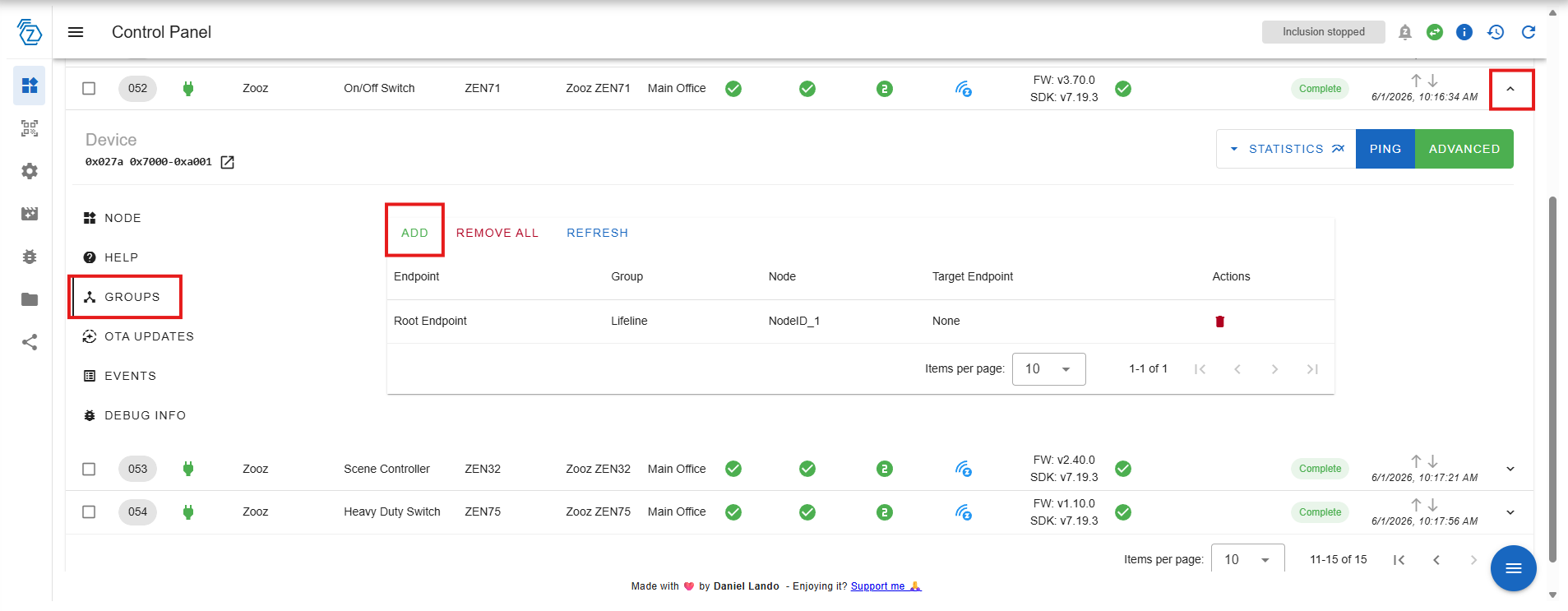
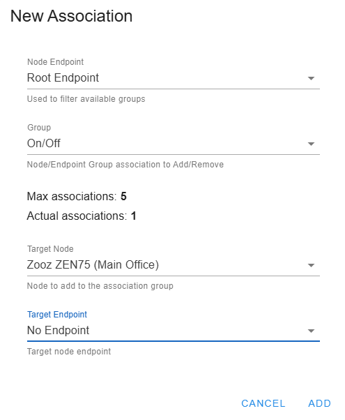
This will open the New Association window. Set the first association:
- Node Endpoint: Root Endpoint. We are selecting Root since there are no other endpoints for this device. If you were utilizing a device with multiple endpoints, like the ZEN30 Double Switch, you would need to select the correct endpoint (such as Endpoint 1 for the dimmer paddle).
- Group: On/Off. (You would select Multilevel if you are working with dimmers)
- Target Node: ZEN32 Scene Controller. This is the remote switch node you are sending the changes to.
- Target Endpoint: No Endpoint. Since the ZEN32 is a single channel device, there is no specific endpoint. This stays as No Endpoint.
Click Add when done.

Repeat the process above, but this time with the third switch. In our example, this is the ZEN75 Heavy Duty Switch:
Your main switch (ZEN71 in this example) will now show two associations:
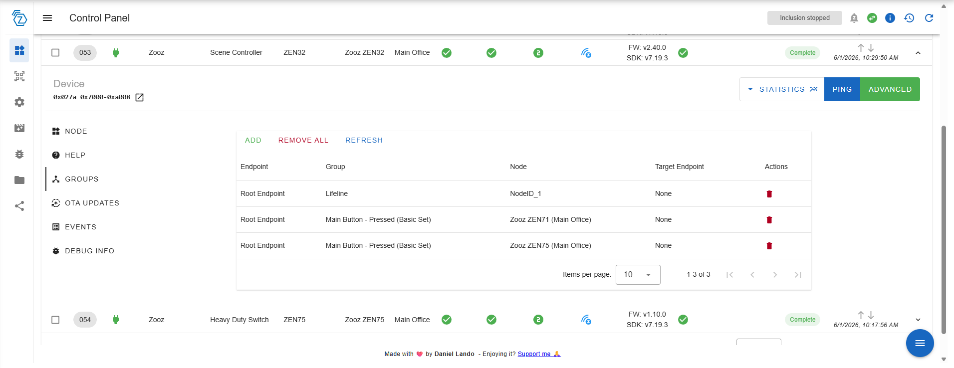
Repeat the process for your first remote switch. In this instance, it is the ZEN32 Scene Controller. We'll be adding the ZEN71 On/Off Switch and the ZEN75 Heavy Duty Switch to the On/Off Group Association. The ZEN32 should show the ZEN71 anbd ZEN75 once you've added the associations:
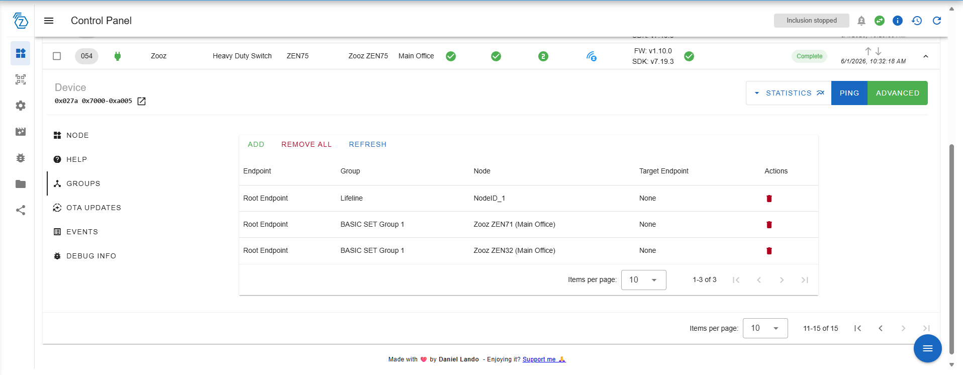
Repeat the process again for the last remote switch (ZEN75 in this example). Add the main switch and the first remote switch. When done, the ZEN75 will show the ZEN71 and the ZEN32 in the association groups:
You can now control the load on the ZEN71 On/Off Switch (physically wired to the load) via all switches in your virtual 4-way.
2. Central Scene
This option uses Z-Wave’s built-in command structure. When you tap, double-tap, or hold a switch button, the switch sends a Central Scene notification directly to the hub. The hub interprets these commands and executes the linked automations, such as turning another switch on or dimming a light. Central Scene programming happens at the protocol level—it’s part of the Z-Wave standard—and doesn’t require you to manually build multiple automations for each possible action. However, in a virtual 4-way the switches themselves don’t stay perfectly synchronized because the LED indicators rely on local device states, not hub commands. Central scene uses the status reported by each switch.
This option would be selected if your switches are included to your hub via Z-Wave Long Range.
Important Notes
-
This type of communication between the devices requires that your hub is active and operational.
-
The paddle on your switch will now be treated like a button on a remote control that's pressed or held - it will send only this information to the hub and should not be treated as an additional on/off device with its own status.
-
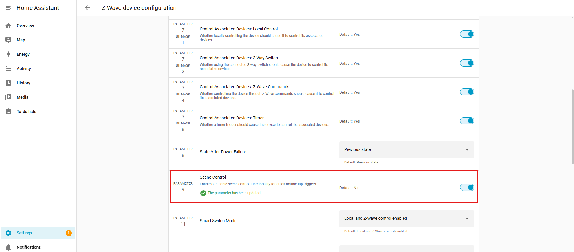
After you add the switch to the hub, you need to go to the advanced settings to enable scene control on your device (if it's disabled by default). If you don't change the setting first, your programming won't work.
When creating a virtual 4-way setup using Central Scene programming, only two of the three switches needs to have Scene Control enabled—the ones that aren’t directly connected to the load.
The load switch (in the below example, a ZEN71 On/Off Switch wired to the light) already controls the light locally. When you press its paddle, it turns the connected load on or off directly through wiring, so there’s no need for it to send scene commands. This switch will simply receive on/off commands from the hub when the remote switches are used.
The remote switches (in the below example, a ZEN32 Scene Controller and a ZEN75 Heavy Duty Switch, that are powered but not wired to the light) are the ones that must have scene control enabled. Because they don’t have a load connection, they rely on Central Scene notifications to tell the hub what action should occur. The hub then runs an automation to control the load switch accordingly.
Example setup:
-
Scene 001 (upper paddle single press) → triggers a hub automation to turn the ZEN71 on
-
Scene 002 (lower paddle single press) → triggers a hub automation to turn the ZEN71 off
When using a dimmer, you can also configure dimming from the remote switches by holding and releasing the paddle and using Start Level Change and Stop Level Change commands.
In short:
-
The remote (no load) switch → Scene Control enabled.
-
The load-connected switch → Scene Control disabled. You can have this enabled if you prefer to use this for other multi-tap options, it simply isn't required in the below virtual 4-way example.
-
The hub manages the logic, translating scene events into load actions.
This method allows full virtual 4-way functionality even when Direct Association isn’t available, such as when the switches are included via Z-Wave Long Range.
Programming Steps
1. In the Z-Wave JS integration for Home Assistant, select your first remote dimmer or switch. In our example, this will be the ZEN75 Heavy Duty Switch. Click the Configure button.
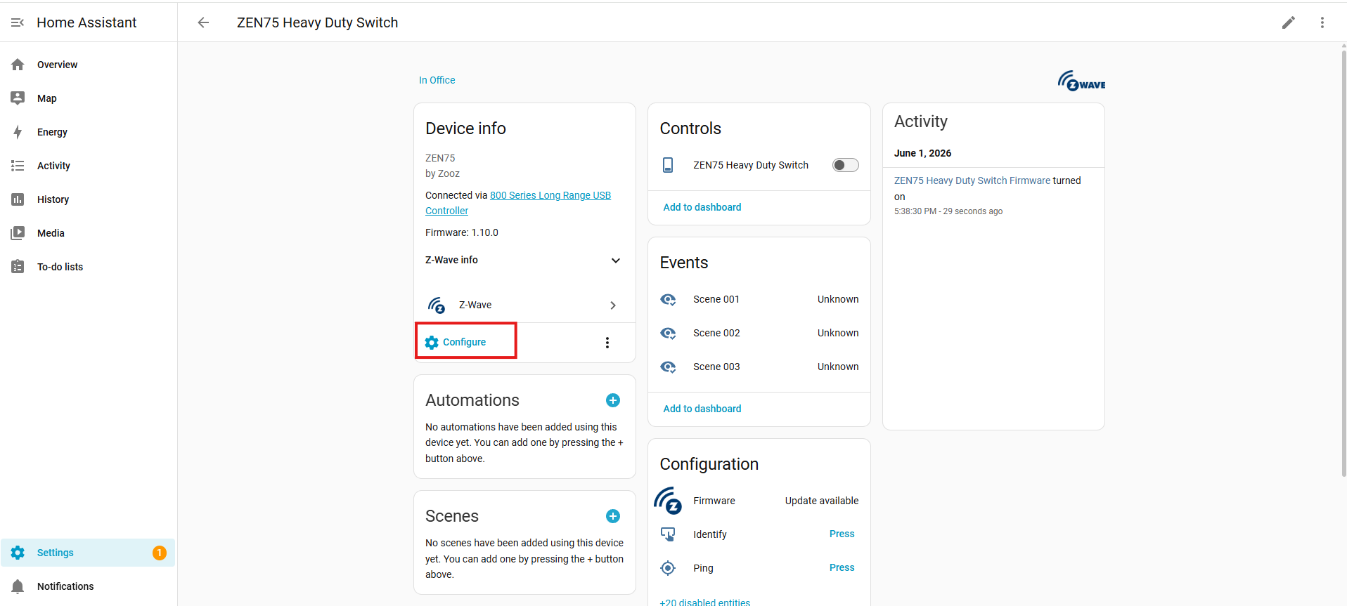
2. Scroll down to the Scene Control parameter and enable it (this only needs to be done on the remote switches).
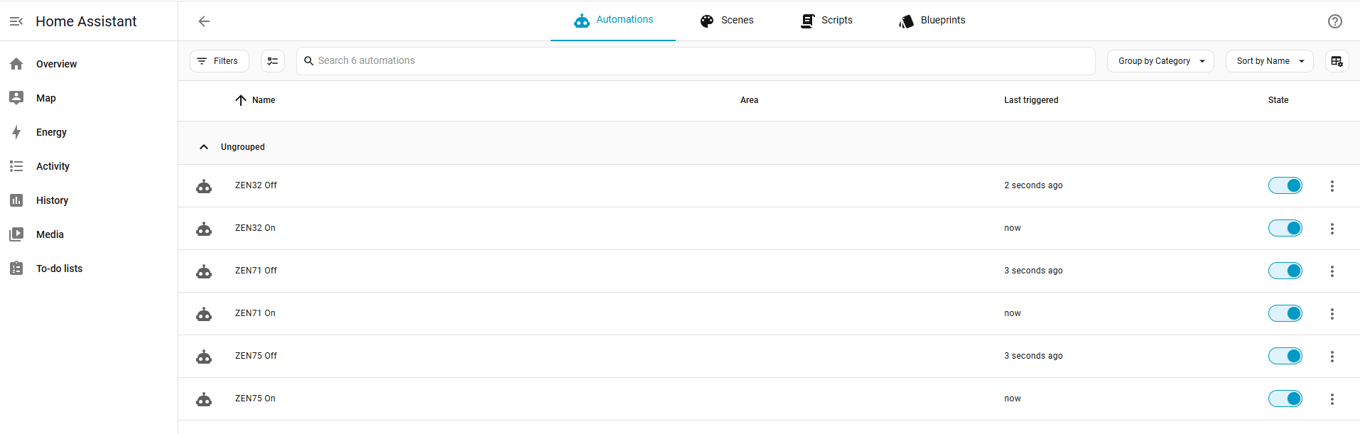
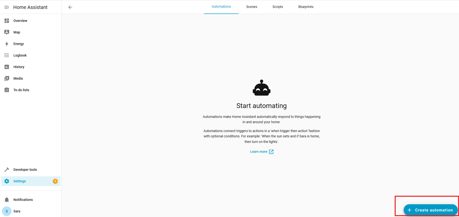
3. Go to Settings > Automations & Scenes.
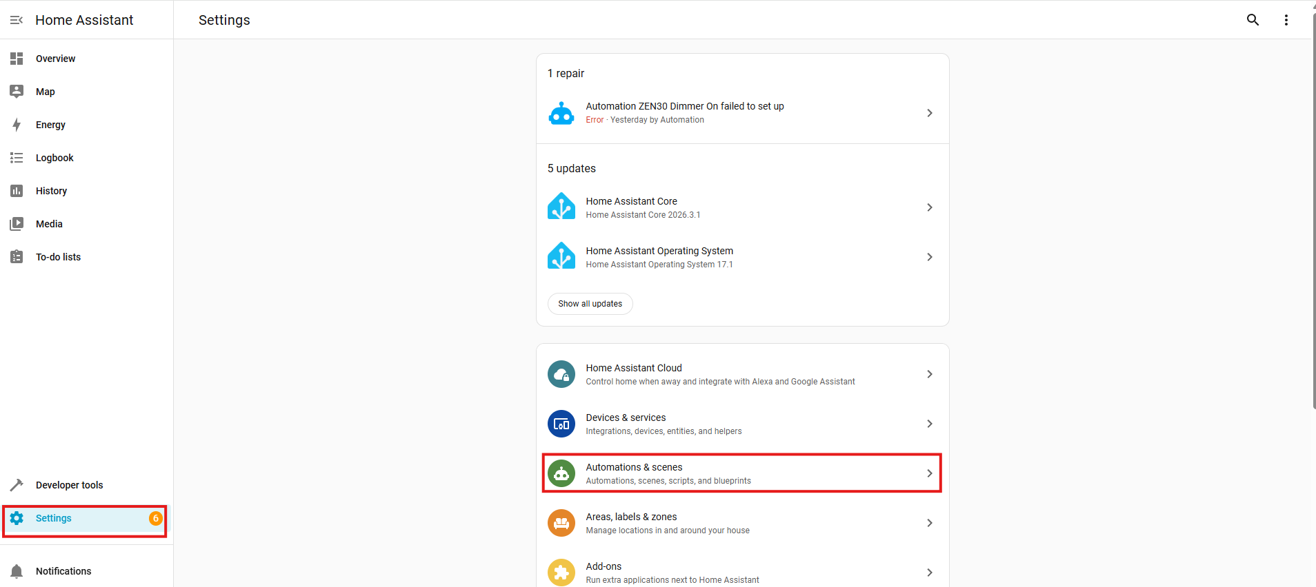
4. Click + Create automation.
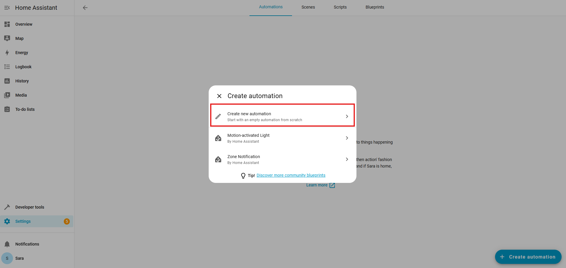
5. Click Create new automation.
6. Under the When section, click + Add trigger.
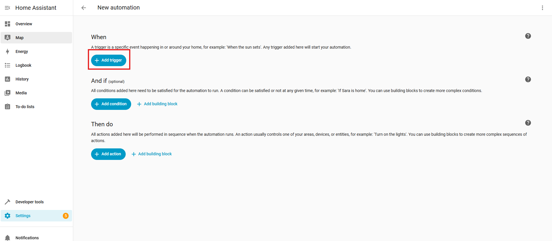
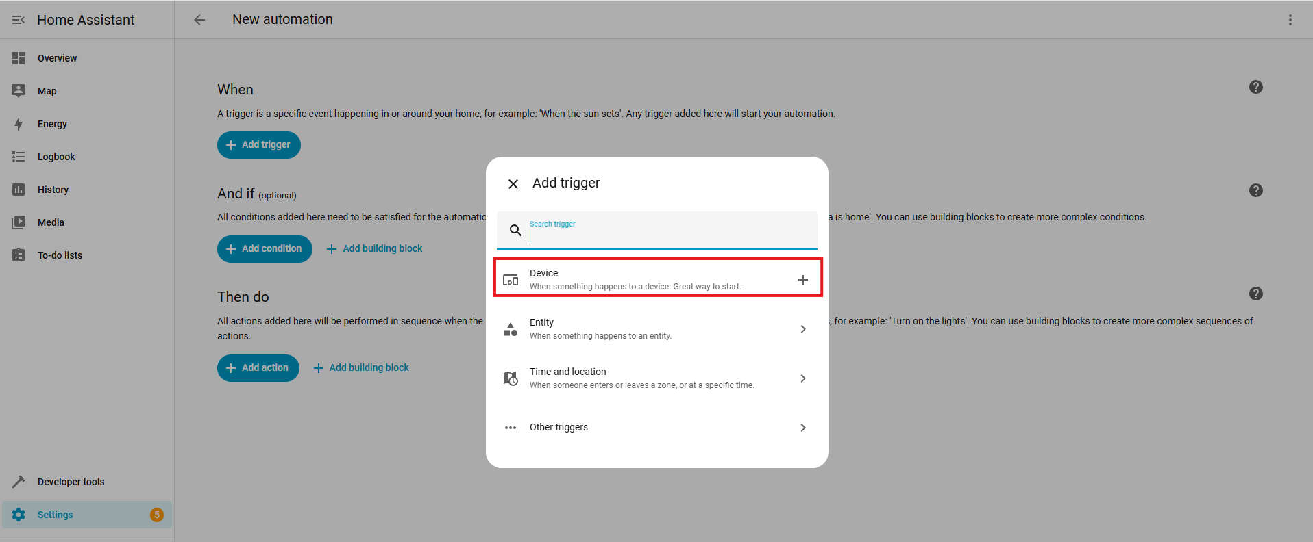
7. Click Device.
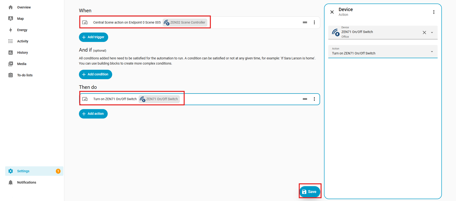
8. Under When, you'll use your central scene trigger. In this instance, we are using the upper paddle of the ZEN75 tapped once to trigger the ZEN71 to turn on. Click Save when done:
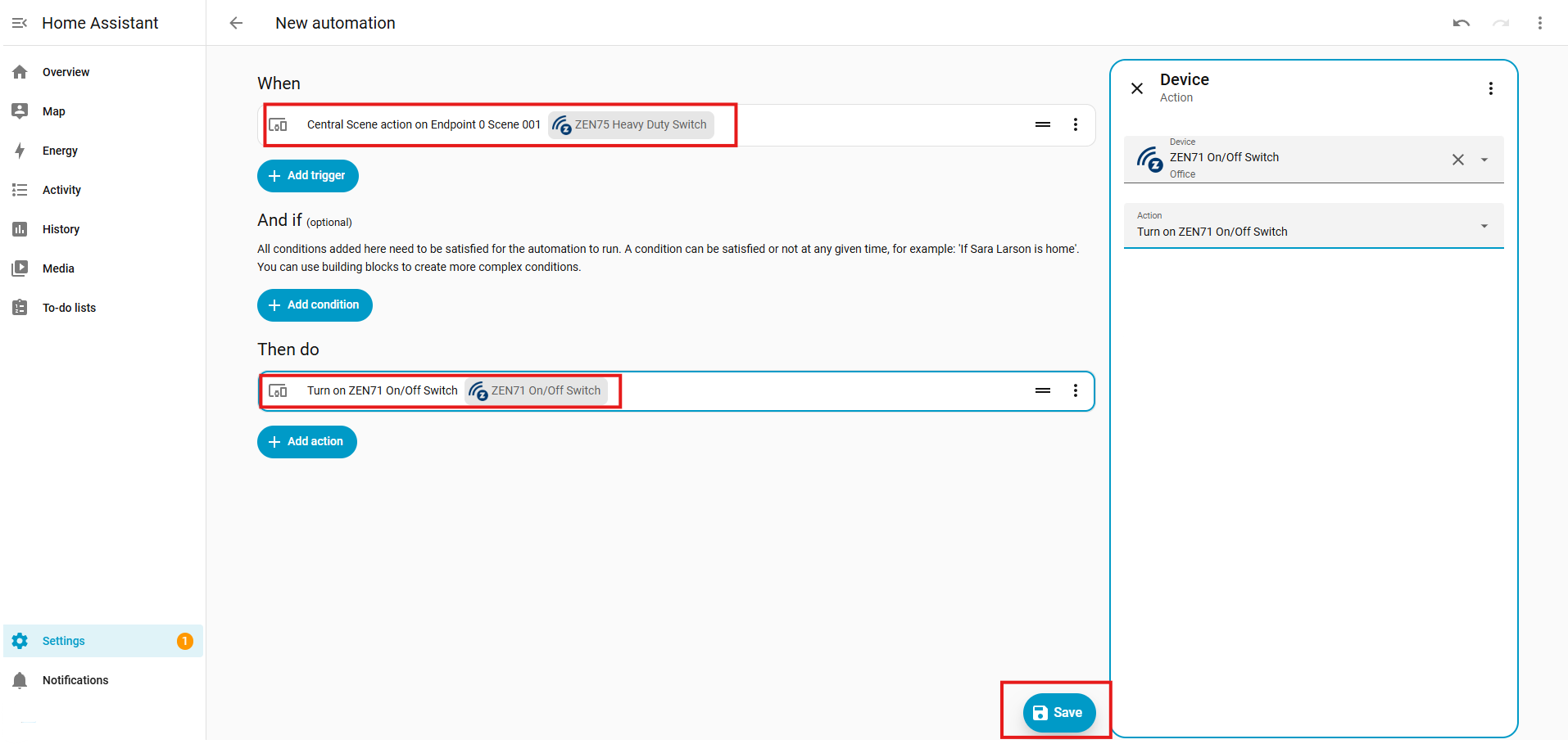
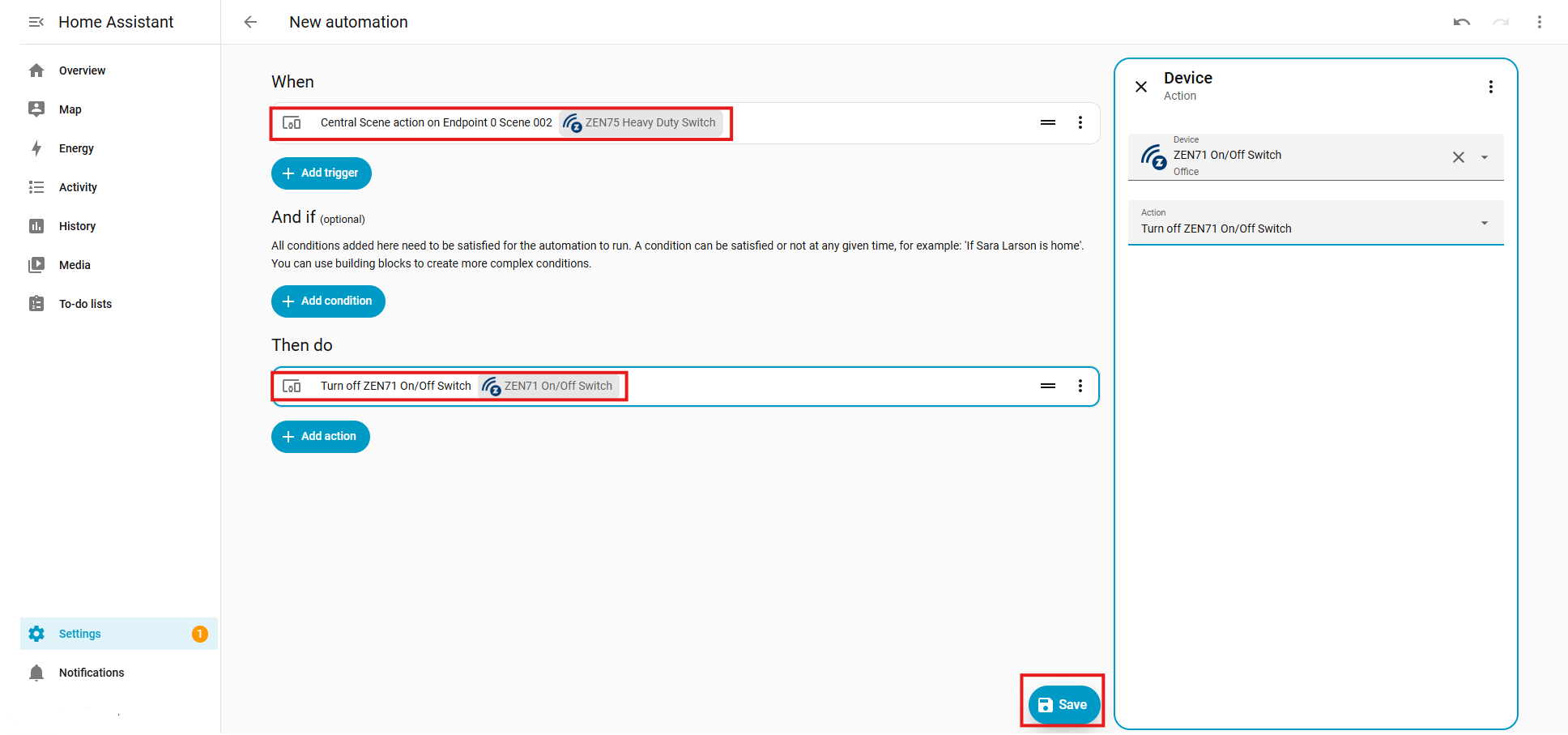
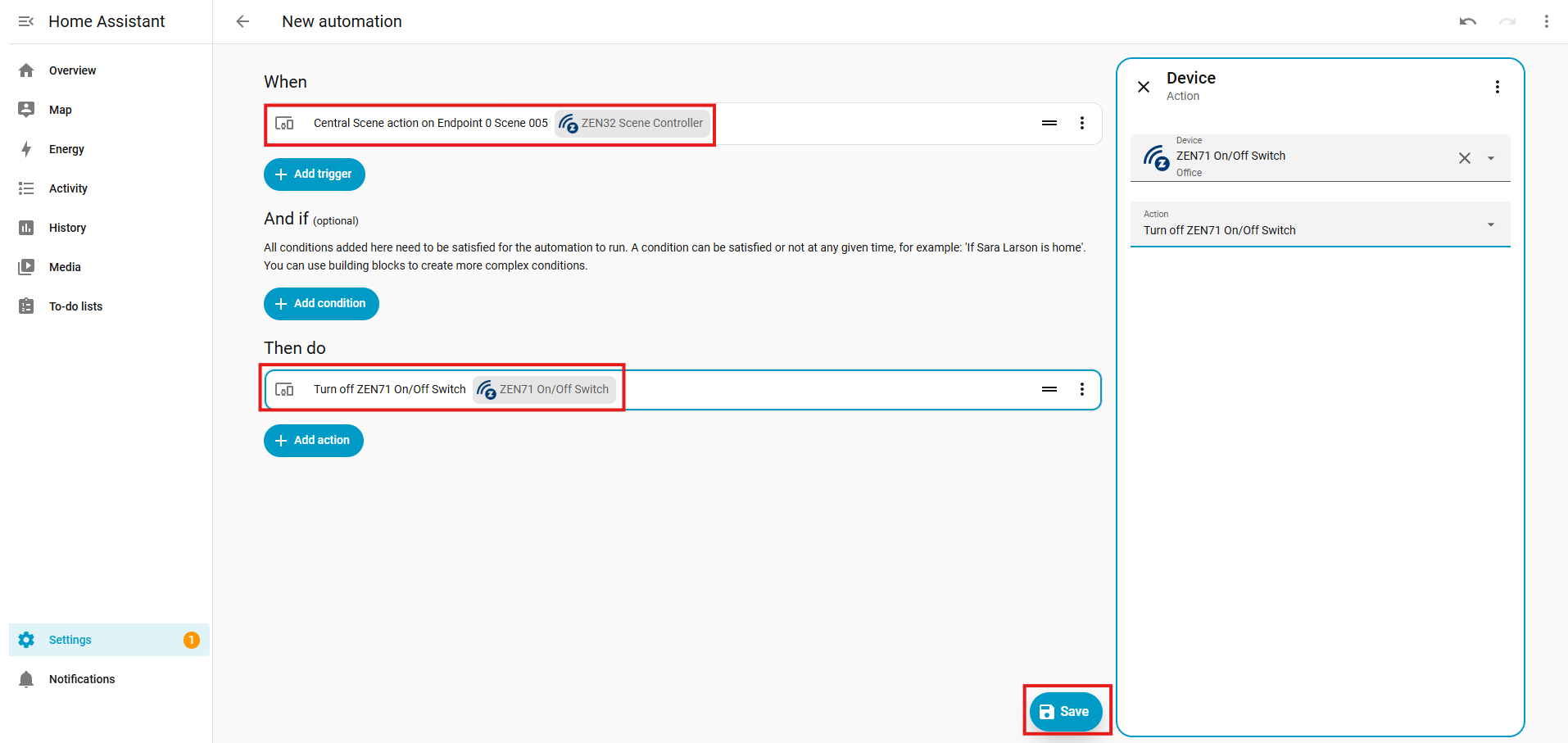
9. Repeat, this time for a single tap on the lower paddle of the ZEN75 to turn off the ZEN71:
10. Repeat the steps for the second remote switch. In our example, this will be the ZEN32 Scene Controller. The main button the ZEN32 is Scene 005, and you'll have one central scene action for on and one for off:
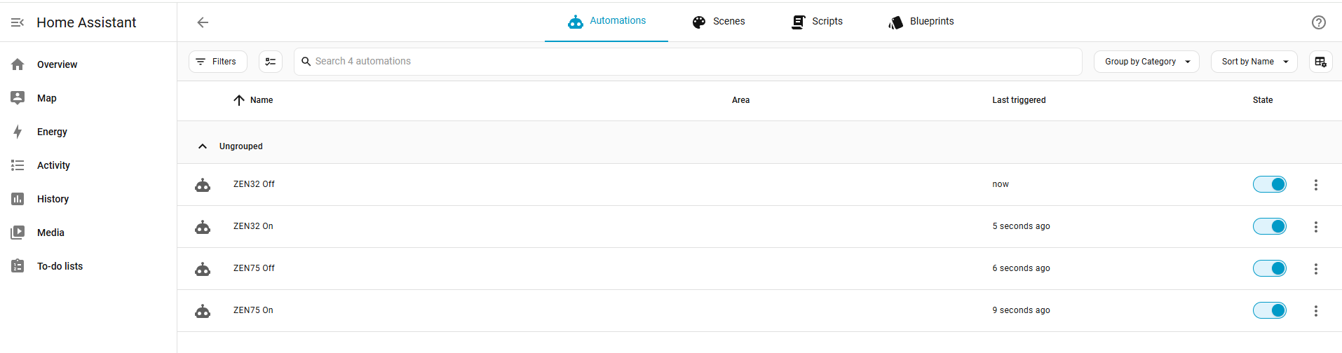
You should now have 4 new central scene automations, and can control your light from any switch in the virtual 4-way:
3. Smart Rules
In most interfaces, this is simply called scenes. This is a higher-level automation feature managed entirely by the hub. Instead of using Central Scene commands, you manually define a set of actions for each event—turn this device on, set that one to 50%, etc. To make three switches behave like a 4-way, you’d typically need six separate scenes: one for turning on from switch A, one for turning off from A, one for turning on from B, one for turning off from B, and one for turning on from C, one for turning off from C. While this keeps all switches synchronized, it generates more Z-Wave traffic and adds complexity, since every state change must be processed by the hub and distributed to all devices involved.
Since Home Assistant supports Direct Association via the Z-Wave JS UI as well as Central Scene, these methods would be recommended, with Smart Rules used as a last resort. The only benefit here is that the smart rules do allow the LED indicators to be synchronized across your devices. With Central Scene, the LED indicators will not be in sync because the LED indicators rely on local device states, not hub commands. Smart Rules would keep the LED indicators in sync, but cause more Z-Wave traffic.
- If switch A (primary switch or dimmer) is turned on, then turn switch B and C on (where B and C are the remote control dimmers or switches).
- If switch A is turned off, then turn switch B and C off.
- If switch B is turned on, then turn switch A and C on.
- If switch B is turned off, then turn switch A and C off.
- If switch C is turned on, then turn switch A and B on.
- If switch C is turned off, then turn switch A and B off.
Programming Steps
You would follow steps 3-7 in the Central Scene programming section above, but now you would select the status of each switch. For example, below we have "when the ZEN71 is turned on, then turn on the ZEN75 and ZEN32."
1. Main switch (ZEN71) on and off scenes:

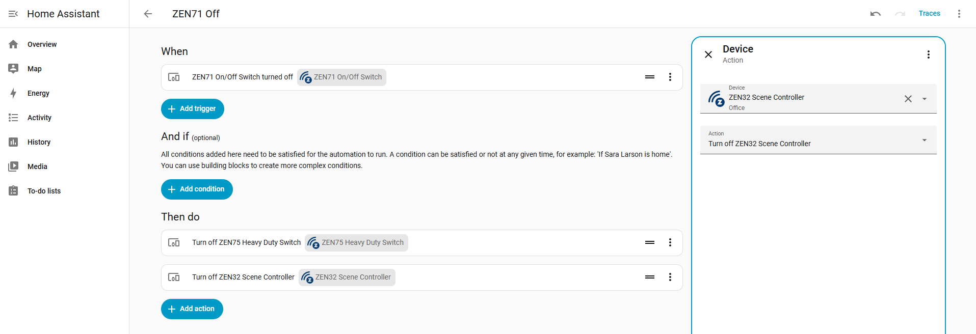
2. Remote switch (ZEN75) on and off scenes:

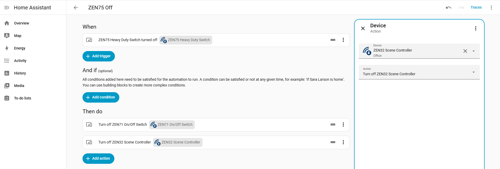
3. Second remote switch (ZEN32) on and off scenes:
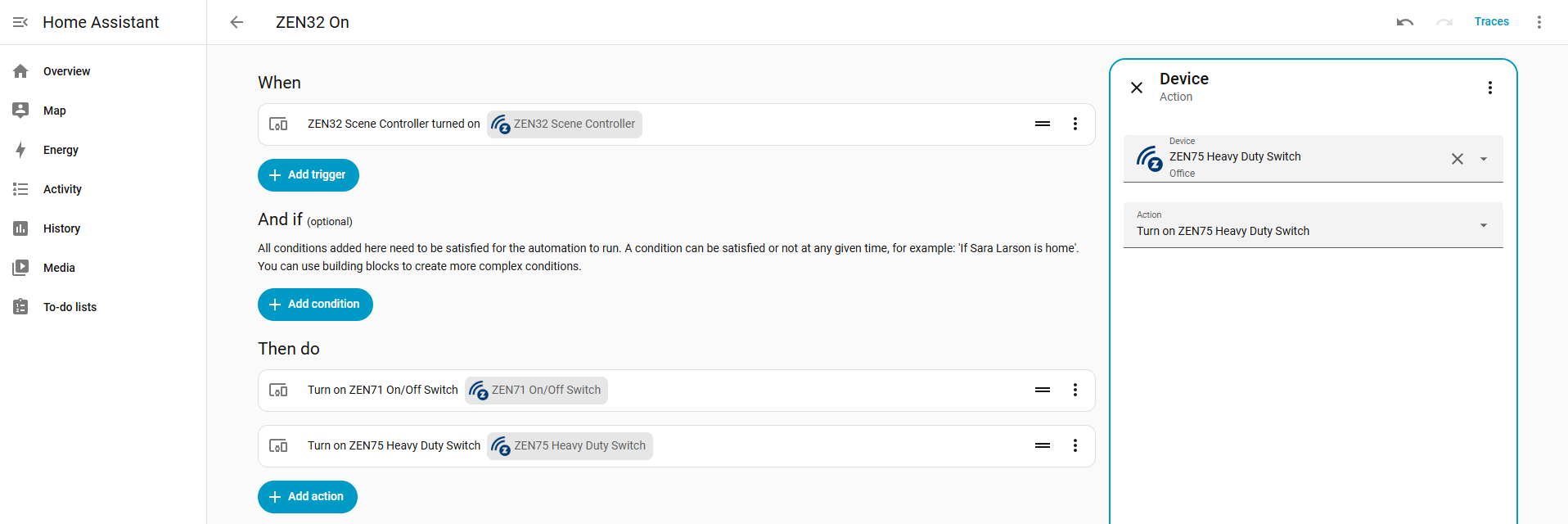

You should now have 6 scenes that will allow you to turn on and off the connected light from any switch in the 4-way installation, while maintaining accurate status and LED indicators on all switches: