This wiring configuration is designed for use with a mechanical, two-wire heat detector connected to the input terminals of the Zooz ZEN58 Low Voltage Relay. The diagram demonstrates how a dry-contact heat detector can be used to report a heat alarm event to your Z-Wave system.
The ZEN58 monitors the detector’s contact state. When the detector activates, the internal contact closes, completing the circuit and signaling an alarm condition to the relay.
Compatible Heat Detector Type
Only mechanical dry-contact heat detectors should be used with this setup.
The correct detector must meet all of the following requirements:
-
Mechanical heat detector using either Rate-of-Rise operation or fixed temperature activation
-
Two-wire configuration
-
Normally open dry contact output
-
Contact closes when the alarm condition is triggered
When the surrounding temperature rises rapidly in a Rate-of-Rise detector, or reaches the fixed activation temperature, the internal mechanical switch closes. The two wires then complete the circuit, which the ZEN58 interprets as an alarm signal.
These detectors were commonly used with older security or fire alarm panels as simple zone inputs.
One example of a compatible model is the System Sensor 5600 mechanical heat detector series, which uses a physical contact closure when activated.
Devices That Are NOT Compatible
The diagram and wiring instructions do not apply to powered or digital detection devices.
Do not use:
- Four-wire powered heat detectors
- Smoke detectors of any type
- Addressable fire system devices
- Sensors requiring external power to operate their alarm output
- Any detector without clearly labeled dry-contact terminals
If the device requires power for its alarm signal output, it is not a dry-contact detector and cannot be connected directly to the ZEN58 input.
Required ZEN58 Configuration
To properly report heat alarms, the ZEN58 must be configured to interpret the input as a heat detector.
Set the following parameter:
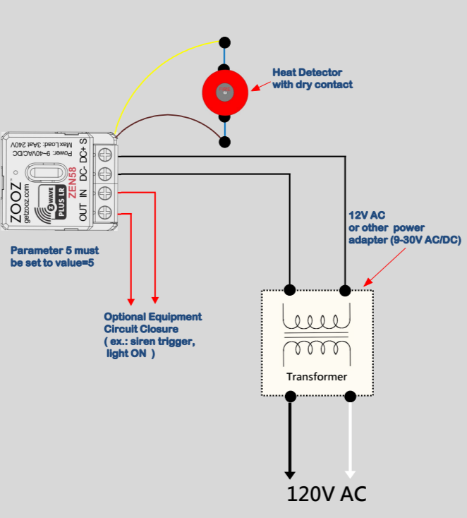
Parameter 5 = value 5
-
This sets the input type to Heat Alarm mode.
After changing this parameter:
-
Exclude the ZEN58 from your Z-Wave network
-
Include the device again
Once re-included, an additional Heat Alarm or Heat Detector entity will appear in your Z-Wave interface for monitoring and automation.
Using the Relay Output with a Heat Detector
In addition to the input terminals, the ZEN58 includes an independent dry-contact relay output that can optionally be used for external control.
Typical applications include:
-
Turning on a warning light
-
Activating a wired siren
-
Switching another low-voltage device
-
Triggering an input zone on a secondary control panel
Default Input-to-Output Behavior
By default, the ZEN58 links the input trigger to the relay output.
This means that when the heat detector activates and closes its contact, the ZEN58 relay will automatically turn ON.
Separating the Heat Input from the Relay Output
If you want the heat detector to be used only for notifications, alerts, or automation logic and not automatically control the relay output, you can disable the automatic linkage.
Set:
Parameter 11 = value 1
-
This setting disconnects the input from directly controlling the relay.
After this change:
-
The Heat Detector entity can be used independently for alerts or automation rules
-
The relay output can be manually controlled or assigned to a separate automation
Wire the ZEN58 Relay
WIRING TIPS: Always take clear, detailed "before" pictures prior to installing the ZEN58. Should you ever need to restore the original set-up, or reach out to us for help, we will need to verify the original wiring to ensure the installation is correct. Always use the correct screwdriver size for the ZEN58 terminals. Please verify you have the proper electrical tools for cutting, prepping, and stripping electrical wires. If you lack the necessary tools to correctly perform the installation or are unsure which tools to use or how, please hire an electrician to complete the installation for you. Please follow the National Electrical Code and your local safety regulations when performing the installation, including (but not limited to), choosing the correct gauge of jumper wires.
POWER OFF: Please verify you have turned off the circuit power in the breaker panel before you start the installation. Keep the ZEN58 removed from its power source while performing the installation.
The diagram below shows how to power the ZEN58 Low Voltage Relay and connect a two wire mechanical heat detector with a normally open dry contact. Follow the connection path below when matching your wiring to the diagram.
1. Power Supply to the ZEN58
The ZEN58 must be powered by a low voltage transformer or power adapter rated between 9 and 30 volts AC or DC.
-
Run the two low voltage output wires from the transformer to the relay:
-
One transformer wire connects to the DC+ terminal on the ZEN58
-
The other transformer wire connects to the DC− terminal on the ZEN58
-
These two wires provide operating power for the relay itself.
The transformer primary side connects to the 120 volt AC mains as shown in the lower portion of the diagram.
2. Heat Detector Input Wiring
The mechanical heat detector connects to the two S input wires coming from the ZEN58:
-
One detector wire → brown S lead
-
The other detector wire → yellow S lead
These S wires are a dry contact sensing input designed to detect a simple contact closure.
Important:
-
No external voltage may ever be applied to the S wires
-
The detector must only open or close a passive mechanical contact
-
The ZEN58 internally senses continuity across these two wires
When the heat detector activates, its internal contact closes and electrically joins the brown and yellow wires. The ZEN58 interprets this closure as an input trigger and reports the heat alarm.
3. Optional Relay Output Wiring
The IN and OUT terminals form a completely separate dry contact relay output that can switch an independent external circuit.
Key points:
-
The relay simply opens or closes this path
-
The relay can switch 0 to 240 volts AC or DC
-
The relay does not supply power on its own
Typical uses include:
-
triggering a siren
-
turning on a warning light
-
closing a control loop
-
activating another panel input
Only wire these terminals if you want the ZEN58 to control external equipment. In the diagram, the red arrows indicate this optional external circuit path. The exact wiring of this portion depends on the device being controlled.