
Don't forget to register your product for extended warranty and more perks:
Click here to register your device here.
FEATURES
-
Powerful dry contact NO/NC relays to control loads up to 20 A for NO
-
Perfect for DC motors, pumps, commercial gates, or HVAC equipment
-
Control up to 2 connected loads independently or together
-
Z-Wave® or optional wall switch control (toggle or momentary type)
-
Monitor inputs independently from output control
-
Built-in timers for each relay to simplify automation
-
Z-Wave® Long Range for ultra reliable no-mesh communication
-
Powered by 12-24 V DC/AC or USB C port for easy set-up
-
Wall mounting and minimal design for clean installation
-
800 series Z-Wave® chip for better range and faster control
SPECIFICATIONS
-
Model Number: ZEN17 800LR
-
Z-Wave® Region: US / CA / MX
-
Power: 12-24 V DC/AC or USB C (DON’T use laptop / tablet chargers)
-
Maximum Load: NO relays: 20 A, NC relays: 10 A
-
Inputs: dry contact or 12-24 V AC/DC (use 1 input type at a time!)
-
Range: Up to 200 feet line of sight (up to 1300 feet with Long Range)
-
Operating Temperature: 32-104° F (0-40° C)
-
Installation and Use: Indoor only
CAUTION
This is an electrical device - please use caution when installing and operating the Universal Relay. Remote control of appliances may result in unintentional or automated activation of power.
Before you install: This device is intended for installation in accordance with the National Electric Code and local regulations. It is recommended that a licensed electrician perform this installation. USE A SINGLE POWER SOURCE AT ALL TIMES.
WHAT'S WHAT
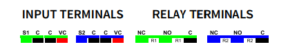
S1 C: wall switch to control R1 or dry contact sensor to monitor leaks (max 40k Ohm when on), open/close status, or motion.
C VC: 12-24 V DC / AC input to control R1. NEVER use C VC and S1 C together! Only one type of input can be used at any given time.
S2 C: wall switch to control R2 or dry contact sensor to monitor leaks, open/close status, or motion.
C VC: 12-24 V DC / AC input to control R2. NEVER use C VC and S1 C together! Only one type of input can be used at any given time.
NC C R1: normally closed relay controlling any load up to 10 A.
NO C R1: normally open relay controlling any load up to 20 A.
NC C R2: normally closed relay controlling any load up to 10 A.
NO C R2: normally open relay controlling any load up to 20 A.
WIRING TIPS
TAKE PICTURES: Before you disconnect any wires, document your set-up and send us images of your existing installation so we can help if needed.
GATHER YOUR TOOLS: Always use the correct screwdriver size for the terminal screws on your Universal Relay and wall switches (if connecting them). Use appropriate electrical tools when cutting, prepping, and stripping electrical wires. If you don’t have the necessary tools to perform the installation or are not sure which tools to use or how, please hire an electrician to complete the installation for you.
SAFETY FIRST: Follow the National Electrical Code and your local safety regulations when performing the installation, including (but not limited to), choosing the correct gauge of jumper wires. The recommended gauge for 15 Amp circuits is 14 AWG and 12 AWG for 20 Amp circuits.
1 POWER SUPPLY AT A TIME: Never use USB C and 12-24 V power supply together. Double power source will damage the device.
1 INPUT TYPE AT A TIME: Never connect inputs to S1 C and VC C for the same relay. Each relay can only have a single input type.
NO VOLTAGE ON “S” TERMINALS: The only input terminals that accept voltage are the C VC terminals.
WIRING: READ IT!
- CHECK THE LOAD: make sure that the connected appliance does not exceed 20 A for normally open relays or 10 A for normally closed relays.
- POWER OFF: turn the circuit power off in the breaker panel before you start. If handling wiring from a box with multiple circuits, turn power off at all of the circuits.
- REMOVE THE WALL SWITCH: if the load is currently controlled by a wall switch, carefully remove it from the box and disconnect the wires from the switch.
- CONNECT THE UNIVERSAL RELAY: follow the instructions in the appropriate diagram for your set-up. If you can’t find your scenario in the diagrams below, please request custom instructions from our support team, we’re happy to help: [email protected].
- HOW TO SECURE WIRES IN TERMINALS: first, unscrew the appropriate terminal’s screw just far enough so there is a clear opening in the terminal for the wire to go in. Make sure the wire is stripped at the right length and perfectly straight before you insert it into the terminal. Once you put the wire in the terminal, carefully screw the terminal screw back in to hold down the wire. Check the connection by gently pulling on the connected wire to make sure it’s fixed securely.
- POWER THE UNIVERSAL RELAY: connect the USB C power source to the MultiRelay or use the “+” “-” terminals on the device to bring low voltage power to it. Never use both at the same time. In both cases you’ll need a standard 1 A power adapter to plug into a standard 120 VAC receptacle. Do NOT use with laptop or tablet chargers, they require a large battery on load to activate.
WIRING EXAMPLE
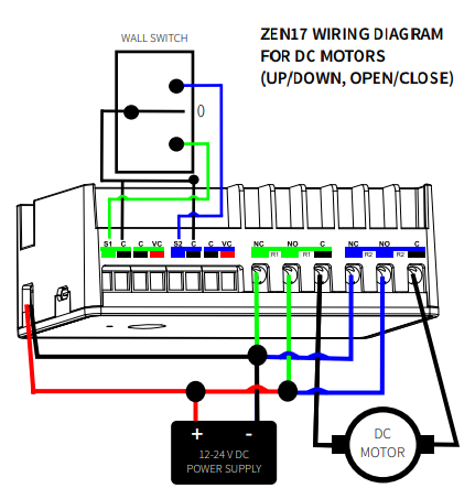
WIRING GUIDE
Here are some general wiring examples on how to use the ZEN17 dry contact relays in the most popular applications. Please make sure you understand how dry contact relays work before proceeding and always request a diagram or custom instructions from us if you’re not sure how to complete your installation. Please do NOT experiment or attempt trial-and-error installation!
- GARAGE DOOR OPENER: How to Use the ZEN17 Universal Relay as a Garage Door Opener
- WHOLE-HOUSE FAN: How to Use the ZEN17 Universal Relay to Control a Whole House Fan
- LANDSCAPE LOW-VOLTAGE LIGHTING: How to Use the ZEN17 Universal Relay with Landscape Lights
- SPRINKLERS: How to Use the ZEN17 Universal Relay as a Sprinkler Controller
Z-WAVE CONTROL
INCLUSION
There are two ways to add the device to your hub:
SmartStart Inclusion:
- DO NOT POWER ON THE DEVICE YET.
- Initiate SmartStart inclusion process in your hub UI or app.
- Scan the ZWave® QR Code present on the product with a controller providing SmartStart inclusion. Power on the device.
- No further action is required and the SmartStart product will be added automatically within 10 minutes of being switched on in the network vicinity.
Manual Inclusion:
- Initiate inclusion (pairing) in the app (or web interface).
- Finalize inclusion at the device. Click the Z-Wave® button 3 times quickly to add the Universal Relay to your network.
- For secure inclusion, enter the 5-digit security PIN, located on the back label of the relay.
- The LED indicator will blink to signal communication and remain on for 2 seconds to confirm inclusion.
Hub Specific Inclusion Steps
How to Add the ZEN17 Universal Relay to Home Assistant
How to Add the ZEN17 Universal Relay to HomeSeer
How to Add the ZEN17 Universal Relay to Hubitat
How to Add the ZEN17 Universal Relay to SmartThings
How to Add the ZEN17 Universal Relay to Z-Box
TROUBLESHOOTING
The Universal Relay won’t add to your system? Try this:
- Initiate EXCLUSION and click the Z-Wave® button 3 times quickly.
- FACTORY RESET the device.
- Bring your Universal Relay closer to the gateway controller (hub), it may be out of range.
- Get more troubleshooting tips for your hub at www.support.getzooz.com.
EXCLUSION (REMOVING / UNPAIRING DEVICE)
- Bring your Universal Relay close to the Z-Wave hub and power it.
- Put the Z-Wave® hub into exclusion mode.
- Click the Z-Wave® button 3 times quickly. Your hub will confirm exclusion and the Universal Relay will disappear from your controller's device list.
Can't Add My ZEN17 Universal Relay to Home Assistant
Can't Add My ZEN17 Universal Relay to HomeSeer
Can't Add My ZEN17 Universal Relay to Hubitat
Can't Add My ZEN17 Universal Relay to SmartThings
Can't Add My ZEN17 Universal Relay to Z-Box
FACTORY RESET
If your primary controller is missing or inoperable, you may need to reset the device to factory settings. To complete the reset process manually, click the Z-Wave® button 4 times quickly, the LED indicator will flash once, then quickly click the Z-Wave® button 4 times again. The LED indicator will flash 3 times to confirm successful reset and will then turn off for two seconds, then the LED indicator will turn on solid. NOTE: All previously recorded activity and custom settings will be erased from the device’s memory.
ADVANCED SETTINGS
The terminology for advanced settings varies depending on your Z-Wave hub. For instance, Hubitat lists them under the Preferences tab, while Home Assistant lists Parameters and SmartThings lists Settings. Despite these differences in naming, the purpose remains the same: configuring consistent behavior for your device.
Full list of customizable settings: ZEN17 Universal Relay Advanced Settings
How to Access the Advanced Settings for the ZEN17 Universal Relay on Home Assistant
How to Access the Advanced Settings for the ZEN17 Universal Relay on HomeSeer
How to Access the Advanced Settings for the ZEN17 Universal Relay on Hubitat
How to Access the Advanced Settings for the ZEN17 Universal Relay on SmartThings
How to Access the Advanced Settings for the ZEN17 Universal Relay on Z-Box
COMMAND CLASSES
This device requires the following command classes to be supported and recognized by your Z-Wave® controller:
COMMAND_CLASS_ZWAVEPLUS_INFO_V2
COMMAND_CLASS_SWITCH_BINARY_V2
COMMAND_CLASS_ASSOCIATION_V3
COMMAND_CLASS_MULTI_CHANNEL_ASSOCIATION_V3
COMMAND_CLASS_ASSOCIATION_GRP_INFO_V3
COMMAND_CLASS_NOTIFICATION_V8
COMMAND_CLASS_TRANSPORT_SERVICE_V2
COMMAND_CLASS_VERSION_V2, COMMAND_CLASS_SENSOR_BINARY_V2
COMMAND_CLASS_MANUFACTURER_SPECIFIC, COMMAND_CLASS_DEVICE_RESET_LOCALLY
COMMAND_CLASS_POWERLEVEL
COMMAND_CLASS_CONFIGURATION_V4
COMMAND_CLASS_MULTI_CHANNEL_V4
COMMAND_CLASS_SECURITY_2
COMMAND_CLASS_SUPERVISION
COMMAND_CLASS_FIRMWARE_UPDATE_MD_V5
ASSOCIATION
This device supports Group 1 with up to 1 devices for Lifeline communication and Groups 2 (for Relay 1) and 3 (for R2) with up to 5 devices each to send BASIC_SET reports when operated manually
WARRANTY
This product is covered under a 12-month warranty and under a 5-year limited warranty once registered. To read the full warranty policy or file a warranty claim, please go to www.getzooz.com/warranty.
IN NO EVENT SHALL ZOOZ OR ITS SUBSIDIARIES AND AFFILIATES BE LIABLE FOR ANY INDIRECT, INCIDENTAL, PUNITIVE, SPECIAL, OR CONSEQUENTIAL DAMAGES, OR DAMAGES FOR LOSS OF PROFITS, REVENUE, OR USE INCURRED BY CUSTOMER OR ANY THIRD PARTY, WHE-THER IN AN ACTION IN CONTRACT, OR OTHERWISE EVEN IF ADVISED OF THE POSSIBILITY OF SUCH DA-MAGES. ZOOZ'S LIABILITY AND CUSTOMER'S EXCLUSIVE REMEDY FOR ANY CAUSE OF ACTION ARISING IN CON-NECTION WITH THIS AGREEMENT OR THE SALE OR USE OF THE PRODUCTS, WHETHER BASED ON NEGLIGENCE, STRICT LIABILITY, BREACH OF WARRANTY, BREACH OF AGREEMENT, OR EQUITABLE PRINCIPLES, IS EXPRESSLY LIMITED TO, AT ZOOZ'S OPTION, REPLACEMENT OF, OR REPAYMENT OF THE PURCHASE PRICE FOR THAT POR-TION OF PRODUCTS WITH RESPECT TO WHICH DA-MAGES ARE CLAIMED. ALL CLAIMS OF ANY KIND ARISING IN CONNECTION WITH THIS AGREEMENT OR THE SALE OR USE OF PRODUCTS SHALL BE DEEMED WAIVED UNLESS MADE IN WRITING WITHIN THIRTY (30) DAYS FROM ZOOZ'S DELIVERY, OR THE DATE FIXED FOR DELI-VERY IN THE EVENT OF NONDELIVERY.
FCC NOTE: THE MANUFACTURER IS NOT RESPONSIBLE FOR ANY RADIO OR TV INTERFERENCE CAUSED BY UNAUTHORIZED MODIFICATIONS TO THIS EQUIPMENT. SUCH MODIFICATIONS COULD VOID THE USER’S AUTHORITY TO OPERATE THE EQUIPMENT. STORE INDOORS WHEN NOT IN USE. SUITABLE FOR DRY LOCATIONS ONLY. DO NOT IMMERSE IN WATER. NOT FOR USE WHERE DIRECTLY EXPOSED TO WATER. This device complies with Part 15 of the FCC Rules. Operation is subject to the following conditions:
-
This device may not cause harmful interference.
-
This device must accept any interference received, including interference that may cause undesired operation.
This equipment has been tested and found to comply with the limits for a Class B digital device, pursuant to part 15 of the FCC Rules. These limits are designed to provide reasonable protection against harmful interference in a residential installation. This equipment generates, uses and can radiate radio frequency energy and, if not installed and used according to instructions, may cause harmful interference to radio communications. However, there is no guarantee that interference will not occur in any given installation. If this equipment causes harmful interference to radio or television reception, the user may try to correct the interference by taking one or more of the following measures:
-
Reorient or relocate receiving antenna.
-
Increase the separation between equipment and receiver.
-
Connect equipment into a separate outlet or circuit from receiver.
-
Consult the dealer or an experienced radio/TV technician for additional assistance.
All brand names displayed are trademarks of their respective holders.
© Zooz 2025

