Many alarm control panels already provide everything needed to integrate smart control and monitoring and the ZEN58 is designed to take advantage of that.
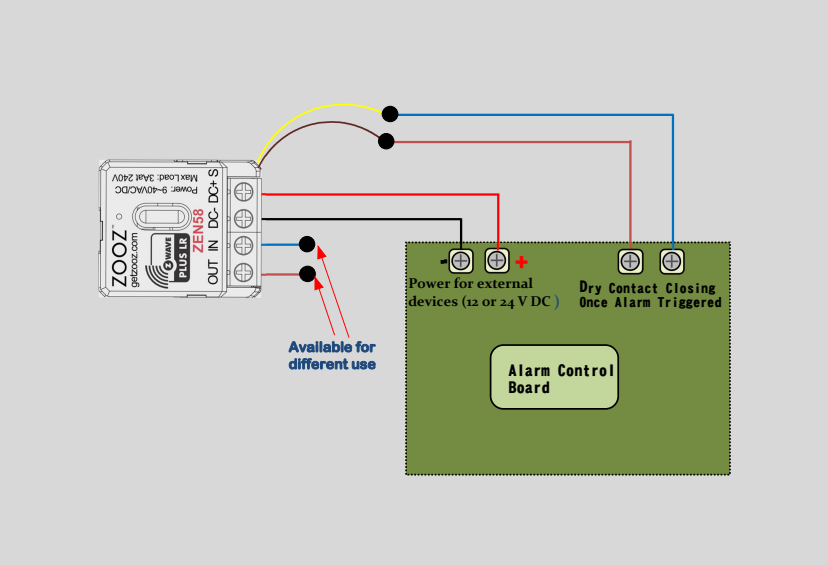
In this setup, the ZEN58 is powered directly from the alarm panel’s auxiliary 12 V or 24 V DC output and uses the panel’s dry contact relay outputs to detect events. When the panel closes a relay for conditions such as a leak, smoke or CO alarm, or a security alert, the ZEN58 can capture that trigger and bring it into your Z Wave system for automation, notifications, or further actions. This diagram shows the general wiring approach for connecting the ZEN58 to an alarm panel output safely and reliably.
General Wiring Tips: Please ensure you take "before" pictures prior to installing the ZEN58. In case you need to restore the original set-up, or reach out to us for input, we will need to verify the original wiring to ensure the installation is correct. Always use the correct screwdriver size. Verify you have the correct electrical tools for cutting, prepping, and stripping electrical wires. If you lack the necessary tools to correctly perform the installation or are unsure which tools to use or how, please hire an electrician to complete the installation for you. Please follow the National Electrical Code and your local safety regulations when performing the installation.
Power Off: Always ensure the circuit power is off in the breaker panel before you start.
Powering the ZEN58
Most alarm control panels provide a 12V or 24V DC auxiliary power output.
You can use this power source to supply the ZEN58 by connecting it to the DC+ and DC- terminals.
Connecting the Alarm Panel Output
Alarm panels typically include dry contact relay outputs that close when a specific event is triggered, such as:
-
Leak alarm
-
Smoke or CO alarm
-
Intrusion or security alert
Connect the alarm panel’s dry contact relay output to the ZEN58 dry contact input terminals. When the panel activates the relay, the ZEN58 will detect the contact closure and convert this signal into a Z-Wave event, allowing you to create automations or push notifications in your smart home system.
Optional Input Behavior Configuration
For this specific use case, you may set Parameter 5 to any value between 5 and 10.
Once set, please exclude and reinclude the ZEN58 from your hub so a new child device can be created for the input of your choise.
You can then set Parameter 11 to value 1.
This disables the input from directly triggering the ZEN58 relay output and allows the dry contact input to be used strictly as a signal input for Z-Wave notifications and automations, while keeping the ZEN58 relay output available for other future applications if needed.