
Use the ZEN58 Low Voltage XS Relay to translate the signals from a keypad to your Z-Wave hub, giving you flexible control without complex wiring or custom hardware.
In this article, we will walk through how to use the ZEN58 with a keypad, focusing on the two most common scenarios. One diagram will cover a keypad that provides a dry contact input, and the other will show a keypad with a latch controlled output. By the end, you will have a clear understanding of how to wire each setup and how the ZEN58 interprets those signals so you can choose the approach that best fits your keypad and application.
General Wiring Tips: Please ensure you take "before" pictures prior to installing the ZEN58. In case you need to restore the original set-up, or reach out to us for input, we will need to verify the original wiring to ensure the installation is correct. Always use the correct screwdriver size. Verify you have the correct electrical tools for cutting, prepping, and stripping electrical wires. If you lack the necessary tools to correctly perform the installation or are unsure which tools to use or how, please hire an electrician to complete the installation for you. Please follow the National Electrical Code and your local safety regulations when performing the installation.
Power Off: Always ensure the circuit power is off in the breaker panel before you start.
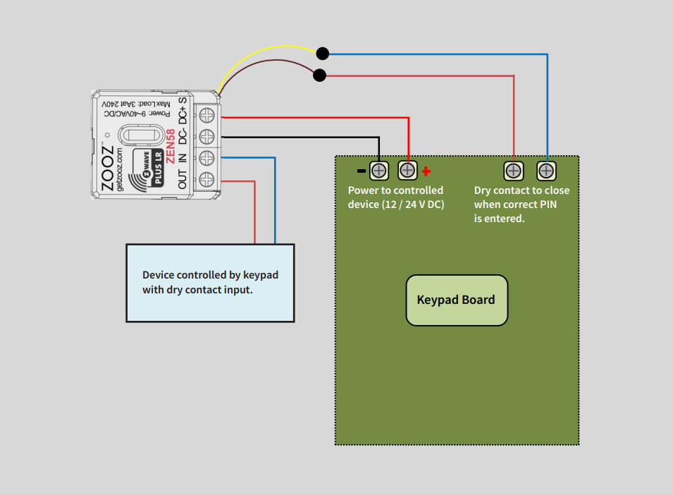
Dry Contact Input Device
1. Power the ZEN58
Use the keypad board’s auxiliary DC output:
-
Keypad +12–24V DC → ZEN58 DC+
-
Keypad GND (–) → ZEN58 DC–
2. Connect Keypad Dry Contact Output to the ZEN58 dry contact inputs
Connect the keypad relay output that closes when the correct PIN is entered:
-
Keypad dry contact terminal → ZEN58 yellow input pigtail
-
Keypad dry contact terminal → ZEN58 brown input pigtail
Do not apply voltage to the ZEN58 input. This is a dry contact input only.
3. Connect the Controlled Device
Use the ZEN58 dry contact relay output (IN and OUT terminals) to connect to device controlled by keypad with dry contact input:
4. Test the System
-
Power on the keypad board
-
Enter the correct PIN
-
Confirm the ZEN58 relay activates and the device turns ON
5. Program the Relay
If you'd like to have the ZEN58 be triggered by the keypad to directly control the connected dry contact input on the ZEN58 relay, no changes to the parameters are required.
Or, you can separate input from output and make custom automations.
-
Set Parameter 5 = 5–10 - this will create additional child devices for the input depending on what is connected. You will need to exclude and reinclude the ZEN58 for the creation of the child device.
-
Set Parameter 11 = 1 - this will disable input to trigger the output (optional). In this case, the automation needs to be setup to trigger the relay based on input.
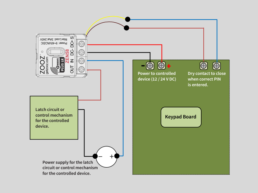
Latch Controlled Device
This wiring setup allows a keypad with a dry contact output to trigger the ZEN58 input, while the ZEN58 relay controls an external latch or low-voltage control circuit.
1. Keypad Power Connection
The keypad board provides auxiliary DC power to the ZEN58:
-
Keypad +12–24 V DC output is connected to ZEN58 DC+
-
Keypad GND (–) is connected to ZEN58 DC–
This powers the ZEN58 module directly from the keypad’s power supply.
2. Connect the Keypad Dry Contact Output to the ZEN58 dry contact inputs
Connect the keypad relay output that closes when the correct PIN is entered:
-
Keypad dry contact terminal → ZEN58 yellow input pigtail
-
Keypad dry contact terminal → ZEN58 brown input pigtail
Do not apply voltage to the ZEN58 input. This is a dry contact input only.
3. Controlled Device Power Circuit
A separate power supply is used to operate the latch or control mechanism:
-
Power supply positive (+) → ZEN58 IN terminal
-
ZEN58 OUT → Positive input of the latch or control circuit
-
Power supply negative (–) → Negative input of the latch or control circuit
When the ZEN58 relay activates, it closes the circuit and delivers power to the controlled device.
Test the System
-
User enters the correct PIN on the keypad.
-
The keypad closes its dry contact output.
-
ZEN58 detects the input trigger.
-
ZEN58 relay energizes.
-
Power is delivered to the latch or control mechanism.

