
Looking to add smart control to your gate opener? The ZEN58 Low Voltage XS Relay makes it possible to automate open, close, and stop functions directly from your smart home system. In this guide, we’ll walk you through how to wire the ZEN58 with your gate opener’s control board, using one relay for each function. Whether you’re upgrading for convenience, security, or remote access, this setup brings your gate into the smart home network with reliable, low-voltage precision.
WHAT YOU NEED
-
A gate opener with Open, Close, and Stop terminals on the control board. If your gate opener only has a pair of terminals that work in sequence, please scroll to the bottom of the article for more details in the Alternate Installation section.
-
3 x ZEN58 Low Voltage Relays
-
Bell wire, such as the one here: 25ft Bell Wire
-
Optional mechanical wall switches (dry contact) can be connected to each ZEN58 to provide manual operation of the Open, Close, and Stop functions.
Once you've confirmed you have everything needed for the install, please follow the instructions below to automate your gate opener on a budget with a DIY solution from the ZEN58 Low Voltage Relay.
WIRING TIPS
-
Before you disconnect any wires, document your set-up so you can send the images to us if any assistance is needed. We always need to see the fully working original installation in order to assist accurately.
-
Always use the correct screwdriver size for the terminal screws on your Z-Wave relay and wall switches (if connecting them).
-
Use appropriate electrical tools when cutting, prepping, and stripping electrical wires. If you don’t have the necessary tools to perform the installation or are not sure which tools to use or how, please hire an electrician to complete the installation for you.
-
Follow the National Electrical Code and your local safety regulations when performing the installation, including (but not limited to), choosing the correct gauge of jumper wires. The recommended gauge for 15 Amp circuits is 14 AWG.
WIRE THE ZEN58 Low Voltage XS Relay
Now that you have assembled all of the parts, it's time to wire in the ZEN58!
POWER OFF: Always ensure the circuit power is off in the breaker panel before you start. Keep the ZEN58 unplugged from its power source while performing the installation.
LOCATION: Install the ZEN58 near the Gate Control Board. You will be using the Gate Control Board to provide power to the ZEN58 Relays.
HOW TO SECURE WIRES IN TERMINALS: Unscrew the appropriate terminal’s screw just far enough so there is a clear opening in the terminal for the wire to go in. Make sure the wire is stripped at the right length and perfectly straight before you insert it into the terminal. Once you put the wire in the terminal, carefully screw the terminal screw back in to hold down the wire. Check the connection by gently pulling on the connected wire to make sure it’s fixed securely.
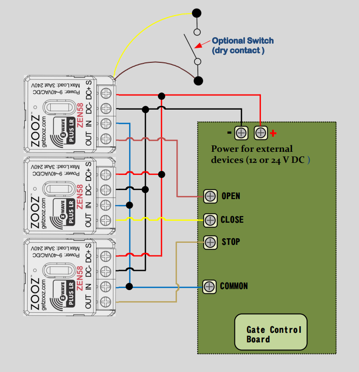
CONNECT THE ZEN58:
-
Use the bell wire (linked above) to connect the Common terminal from the Gate Control Board to the IN terminal on each ZEN58.
-
Connect each OUT terminal on the 3 ZEN58 individually to the STOP, OPEN, and CLOSE terminals on the Gate Control Board.
-
Connect the DC- terminal on each ZEN58 unit to the - terminal on the Gate Control Board.
-
Connect the DC+ terminal on each ZEN58 unit to the + terminal on the Gate Control Board.
CONNECT THE OPTIONAL SWITCHES: You can connect a mechanical wall switch (dry contact) to each ZEN58 to provide manual operation of the Open, Close, and Stop functions. Please note we have a single switch connected to keep the diagram simple and uncluttered. The other two optional wall switches would be connected to the remaining two ZEN58 Relays in the same manner shown.
Verify your wiring is correct; once confirmed, turn the power back on to the Gate Control Board.
INCLUDE THE ZEN58 LOW VOLTAGE RELAYs TO YOUR HUB
How to Include the ZEN58 Low Voltage Relay to Home Assistant
How to Include the ZEN58 Low Voltage Relay to HomeSeer
How to Include the ZEN58 Low Voltage Relay to Hubitat
How to Include the ZEN58 Low Voltage Relay to SmartThings
How to Include the ZEN58 Low Voltage Relay to Z-Box
How to Include the ZEN58 Low Voltage Relay to Your Z-Wave Hub
PROGRAM THE ZEN58 Low Voltage XS Relays
You will need to be able to access the advanced settings for the device via your hub interface. We've provided the instructions below for the most common hubs:
How to Access the Advanced Settings for the ZEN58 Low Voltage Relay on Home Assistant
How to Access the Advanced Settings for the ZEN58 Low Voltage Relay on HomeSeer
How to Access the Advanced Settings for the ZEN58 Low Voltage Relay on Hubitat
How to Access the Advanced Settings for the ZEN58 Low Voltage Relay on SmartThings
How to Access the Advanced Settings for the ZEN58 Low Voltage Relay on Z-Box
Once you've accessed the settings as instructed above, please set the following on all 3 of the ZEN58 Relays:
-
Parameter 5 (Input Type) set to value 11 (Garage Door Mode)
This sets each relay to a momentary behavior.
ALTERNATE INSTALLATION
Some gate opener systems do not have the third STOP terminal available. These units generally have one pair of terminals that work in sequence instead (OPEN_STOP_CLOSE_STOP_OPEN).
For this type of scenerio, please contact us and provide the following information:
1. A link or PDF of the manual to the gate opener. Please ensure the information provided contains the following:
-
Specs with Voltage, Amperage, and Wattage
-
Wiring diagram for the device
2. Images of the existing wiring (.JPG or .JPEG format). Please ensure your images contain the following:
-
All wires involved in the installation,
-
Where all wires connect on the device and from the source (both ends of each wire)
3. Confirmation if there is an existing switch currently controlling the device?
-
If yes, what kind of switch and do you plan to maintain control from the switch? (Momentary, toggle, push button, etc.)
5. What hub/Z-Wave system you are/will be using with the device so we can verify compatibility?
6. If you are requesting a custom wiring diagram, please register your device in our Product Registration Portal. Registration provides direct access to custom instructions and expedited support.

