

The Zooz ZEN32 is a powerful Z-Wave scene controller featuring five customizable physical buttons. Each button can be individually programmed to trigger automations through Central Scene commands or to directly control other Z-Wave devices using Direct Association. This dual-mode capability allows users to choose between flexible, hub-based automation logic or simple device-to-device control. Whether you're aiming to activate complex Home Assistant scenes or simply control a nearby light switch, programming the ZEN32 offers a smart and adaptable solution for seamless home automation.
Below, we'll cover what Central Scene and Direct Association are and how you can program either option on Home Assistant.
We've included two methods for programming below, Direct Association and Central Scene. We would recommend reading more about Direct Association programming here before choosing the best programming method.
Zooz products are officially integrated with the Z-Wave Plus and the Z-Wave JS Front-End of HomeSeer. If you're experiencing issues with accessing the advanced settings of your device or the unit not properly displaying, we would recommend first updating to the Z-Wave Plus or the Z-Wave JS Front-End, then excluding and re-including your device to your network in order for it to be recognized correctly.
Central Scene / Scene Control
Central scene programming allows a Z-Wave device (usually a controller like a switch or remote) to send scene activation commands to the hub or gateway. The hub interprets these commands and determines what actions to take. This method requires the Z-Wave hub or controller to process the commands and execute the automation. Some benefits of using central scene is that you can program multiple actions based on button presses, such as single tap, double tap, triple tap, and press-and-hold gestures. It offers high flexibility in automations, as the hub can trigger complex scenes involving multiple devices and conditions.
The Zooz ZEN32 is a Z-Wave scene controller with 5 physical buttons, all capable of triggering Central Scene commands. This means every button can be used to trigger hub-based automations based on how it’s pressed — no need for direct device associations (unless you want them). Each button on the ZEN32 sends a Scene Number, and different press types (tap, hold, release, etc.) are distinguished by Key Attributes.
Scene Numbers and Button Mapping
Here's how the ZEN32 buttons are mapped to Central Scene scene numbers:
|
Button |
Scene Number |
Description |
|
Switch Button |
|
The large center button |
|
Button 1 |
|
Small button, top left |
|
Button 2 |
|
Small button, top right |
|
Button 3 |
|
Small button, bottom left |
|
Button 4 |
|
Small button, bottom right |
|
ZAC99 (if used in 3-way) |
|
Reports separately when used |
Each button supports 7 key attributes (aka action types):
|
Key Attribute |
Action Type |
|
0 |
Key Pressed Once |
|
1 |
Key Released |
|
2 |
Key Held Down |
|
3 |
Key Pressed 2x |
|
4 |
Key Pressed 3x |
|
5 |
Key Pressed 4x |
|
6 |
Key Pressed 5x |
So for example:
-
Pressing Button 1 once = Scene 1, Key Attribute 0
-
Holding Switch Button = Scene 5, Key Attribute 2
-
Double tapping Button 3 = Scene 3, Key Attribute 3
ZEN32 + ZAC99 Momentary in 3-Way Setup
Are you looking to have scene control options from the other locations when installing the ZEN32 in a multi-way location? You can use the ZAC99 Momentary switch in the other location(s) in your multi-way installation and use the reported events to trigger scenes.
This option is not available from a standard, dumb on/off switch because the ZEN32 is designed to trigger scenes based on momentary inputs—quick presses that send a signal to activate a programmed scene. A standard "dumb" on/off switch physically changes the electrical state (open or closed circuit) instead of providing the momentary signal input. With a momentary switch like the ZAC99, the ZEN32 consistently receives clean, simple press events it can interpret correctly to trigger scenes, ensuring smooth and reliable scene control.
The ZAC99 is SPST and only the top portion of the switch is pressed. If you click the switch once, it will turn on. If you press and hold it while it's on, it will decrease brightness (when connected with a dimmer in a 3-way). If you click it again, it'll turn off. Once off, when you press and hold it will increase brightness.
If you're wiring a ZAC99 momentary switch to the ZEN32 to control it from another location (e.g. a 3-way circuit), the ZAC99 will trigger Scene 6 with the same key attributes:
|
Device |
Scene Number |
|
ZAC99 |
|
This allows the hub to recognize the input from the remote switch and automate accordingly.
For example:
-
Tapping ZAC99 once = Scene 6, Key Attribute 0
-
Holding ZAC99 = Scene 6, Key Attribute 2
This gives you full automation capability from both the ZEN32 and the auxiliary switch location.
Summary
-
The ZEN32 uses scene numbers 1–5 for its built-in buttons.
-
Each button supports 7 types of press actions via key attributes.
-
If a ZAC99 momentary switch is wired for remote control, it reports as Scene 6.
-
Your hub can create distinct automations for each combo of button and press type.
Programming Central Scene
We've included the steps for programming central scene via the Z-Wave Plus plugin:
1. Select Events:

2. Click on the + symbol to add new event and name it:

3. Select Newly Made Event and go through drop down menus. We recommend selecting the device first, "Central Scene" variant

4. Make sure to select the trigger type as listed for scene control. The trigger VALUE is for specific function requested that triggers the scene:

5. Go through "THEN" drop down menus, selecting the type of action to be done, i.e. "control a device":

6. Select the device/s to be controlled or affected:

7. Select the specific action to be taken (on, off, dimmer % etc.):

Direct Association
Direct association is a direct link established between two Z-Wave devices where one of them acts as the trigger and the other acts as the receiver of that trigger. For example, if you associate a Z-Wave light switch to a motion sensor, the light switch will turn on anytime motion is triggered, without the hub getting involved or without the need to set up an automation for it. In other words, one Z-Wave device sends a direct message to another Z-Wave device, bypassing the hub. These are usually very simple unconditional commands like "on/off" or "dim/increase brightness". The communication works one way without any feedback to the other device. The controlling device simply sends the command to the controlled device or devices associated in what we call "association group". The controlling device is not affected by the controlled device at all, even though there is a link established between the two, it only ever works in one direction.
Association Groups
The association groups supported by the ZEN32 can be found in the device manual, in the Advanced Settings document, and we've included them below as well:
Group 1: Lifeline to hub
Group 2: Main button (5) basic set (pressed only, doesn’t send anything when switch turned on via hub)
Group 3: Main button (5) multilevel (held)
Group 4: Small button #1 basic set (pressed)
Group 5: Small button #1 multilevel (held) > in sequence > held = increase brightness, release = stop level, held = decrease brightness, release = stop level
Group 6: Small button #2 basic set (pressed)
Group 7: Small button #2 multilevel (held) > in sequence > held = increase brightness, release = stop level, held = decrease brightness, release = stop level
Group 8: Small button #3 basic set (pressed)
Group 9: Small button #3 multilevel (held) > in sequence > held = increase brightness, release = stop level, held = decrease brightness, release = stop level
Group 10: Small button #4 basic set (pressed)
Group 11: Small button #4 multilevel (held) > in sequence > held = increase brightness, release = stop level, held = decrease brightness, release = stop level
Limitations and Considerations
Security Level: Before attempting association, double check that both devices are added with the exact same level of security; if one device is included with S2A and one is included with S0, the association will not be available.
Z-Wave Long Range: Please also note that Direct Association is not an option if the device is included via Z-Wave Long Range. ZWLR is device-to-hub direct communication; there are no repeaters and no mesh and the ZWLR devices do not communicate with each other, so direct association programming is not an option for devices included via ZWLR.
You can read more about the requirements, limitations, and recommendations for programming using Direct Association here.
Programming Direct Association
1. Select Plugins:

2. Select Z-Wave Plus and click "Manage Associations":

3. Go through drop down menus, selecting the Z-Wave network, devices to be associated, and the association group:


4. A message will appear below saying if the association was successful or if an error was encountered:

Programming the LED Indicators
Do you want the LED indicators on your ZEN32 to reflect the status of the device controlled by each button? The buttons on the ZEN32 act more like buttons on a remote control than traditional light switches. When a button is pressed, the ZEN32 sends a command to HomeSeer or directly to an associated Z-Wave device. However, the ZEN32 does not automatically receive the current status of the device being controlled. This means that the LED indicator may not remain synchronized with the controlled device, especially if that device can also be operated from another switch, automation, app, or voice assistant.
To keep an LED indicator synchronized with the actual status of a controlled device, create two HomeSeer events:
- One event that turns the LED indicator on when the controlled device turns on
- One event that turns the LED indicator off when the controlled device turns off
The HomeSeer Z-Wave Plus plugin can change Z-Wave configuration parameters as an event action, allowing the ZEN32 LED indicators to be updated automatically. You can find the complete list of available LED parameters and values in the ZEN32 Advanced Settings.
LED Mode Parameters
Use the appropriate LED mode parameter for the button you want to program:
|
ZEN32 button |
LED mode parameter |
|---|---|
|
Main relay button |
1 |
|
Button 1 |
2 |
|
Button 2 |
3 |
|
Button 3 |
4 |
|
Button 4 |
5 |
The LED mode values are:
|
Value |
LED behavior |
|---|---|
|
0 |
LED on when the button is off |
|
1 |
LED on when the button is on |
|
2 |
LED always off |
|
3 |
LED always on |
All LED mode parameters use a size of 1 byte.
For example, to have the LED for Button 4 reflect the status of a bedroom light:
- When the bedroom light turns on, set parameter 5 to value 3
- When the bedroom light turns off, set parameter 5 to value 2
Setting the LED Color
The LED color can be configured separately using the following parameters:
|
ZEN32 button |
LED Color Parameter |
|---|---|
|
Main relay button |
6 |
|
Button 1 |
7 |
|
Button 2 |
8 |
|
Button 3 |
9 |
|
Button 4 |
10 |
Available color values are:
|
Value |
Color |
|---|---|
|
0 |
White |
|
1 |
Blue |
|
2 |
Green |
|
3 |
Red |
|
4 |
Magenta |
|
5 |
Yellow |
|
6 |
Cyan |
All LED color parameters use a size of 1 byte.
The color only needs to be set once unless you want the color itself to change as part of an automation. For example, setting parameter 10 to value 1 will make the Button 4 LED blue.
Create the LED-On Event
Our example below shows how to set the LED behavior, but you can also elect to customize the color and brightness level for the LED indicator as well following the same general outline.
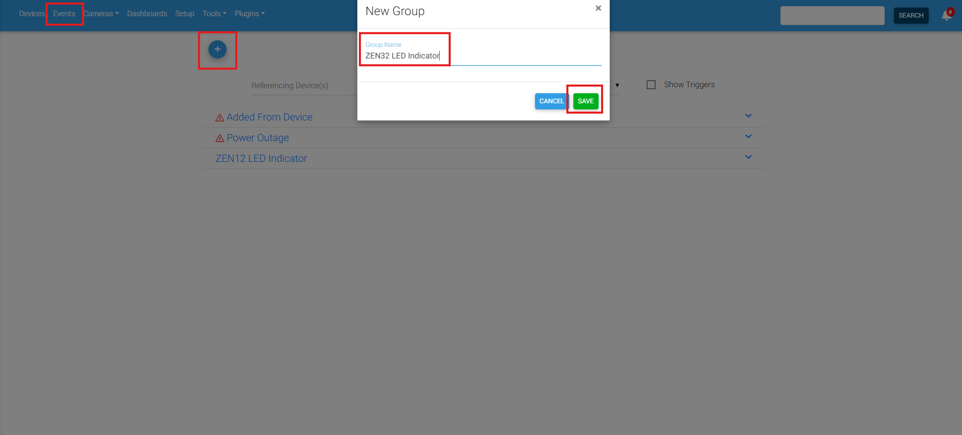
1. Go to Events in HomeSeer > Click the + symbol to create a new event and enter a descriptive name:
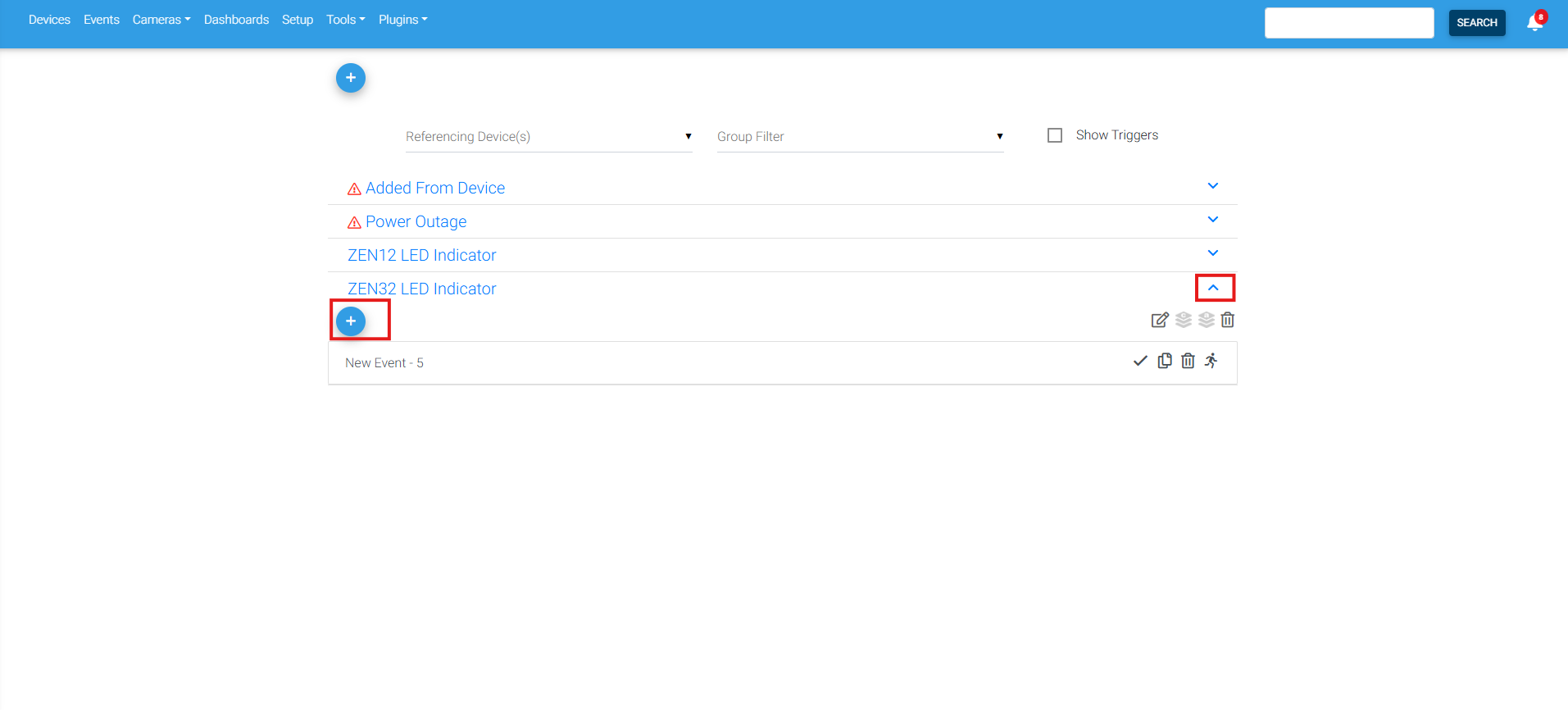
2. In the WHEN section, select the controlled device as the trigger. This is the device that you want the LED indicator on the ZEN32 to display the status for. Configure the trigger to run when the device changes and becomes On:
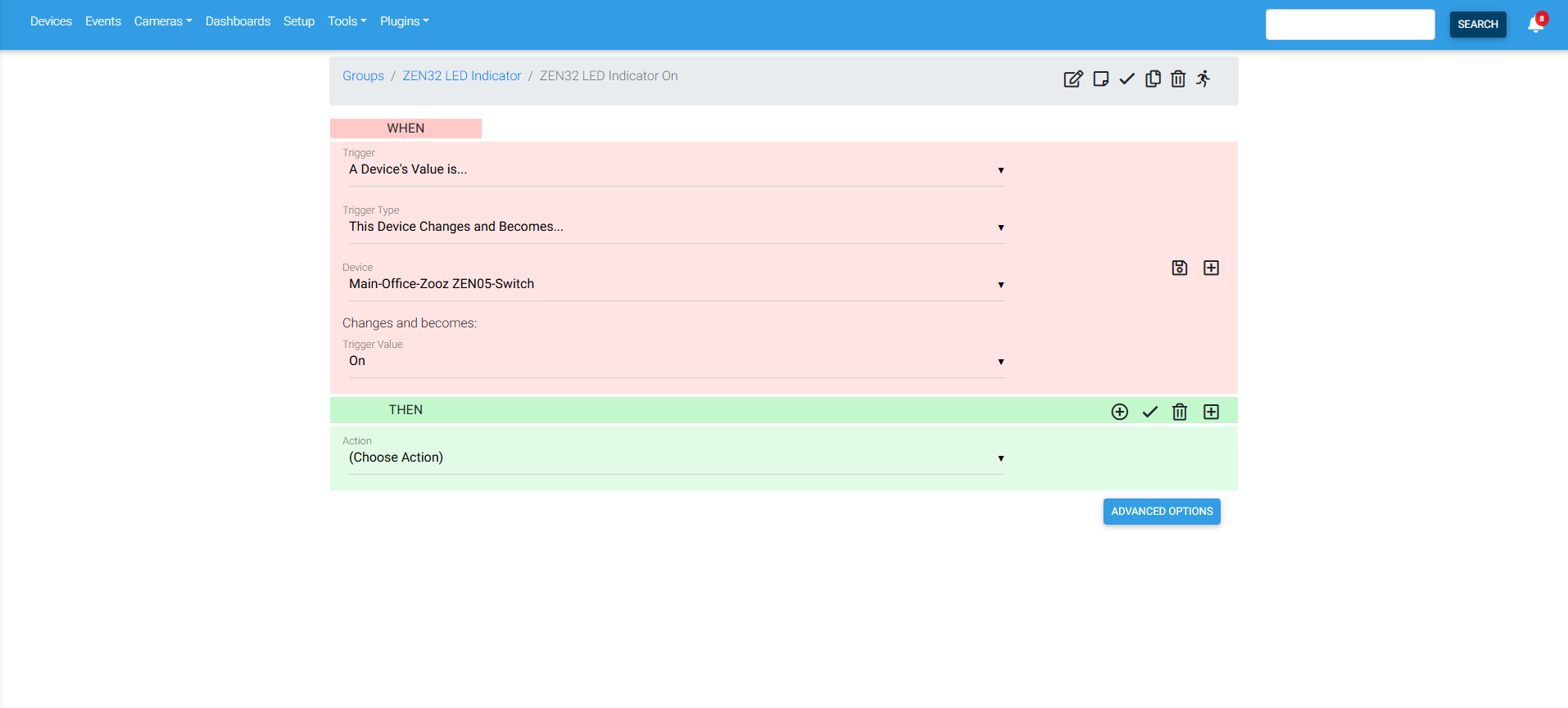
In the THEN section, select a Z-Wave Plus action > select the option to Set a Configuration Parameter Value > select the ZEN32 Scene Controller > enter the LED mode parameter corresponding to the button you want to program > Select a parameter size of 1 byte > enter a value of 3 to set the LED to always on > save the event.
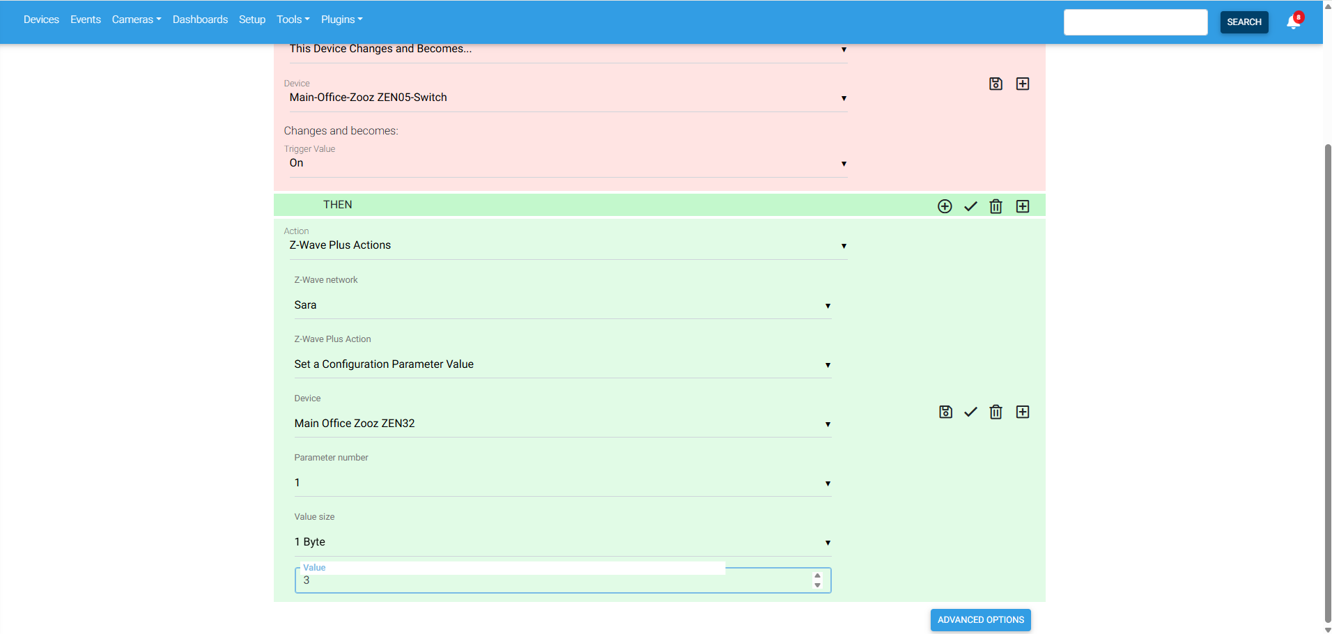
Create a second event following the blueprint above, just setting the value to 2 for always off when the status of the controlled device is off. You can customize this further with LED colors and brightness levels, but the above example gives a handy blueprint on how to call parameter configuration changes via events in HomeSeer.
Recommended Settings for LED Automations
The ZEN32 normally flashes its LED indicators when a setting is changed or when a button is pressed. If you are using the indicators to display device status, these flashes may temporarily interfere with the status display.
For consistent LED behavior, set the following parameters to value 1:
-
Parameter 23: Disable LED flash when a setting is changed
-
Parameter 27: Disable LED flash when a button is pressed
Both parameters use a size of 1 byte.
One important efficiency note: I would recommend telling users to set the color separately rather than placing both the mode and color parameter changes in every status event. Otherwise, every state change sends two configuration commands to the ZEN32 when only the mode parameter actually needs updating.
Please let us know if you have any questions!

